Computer News 80

Open forum for users of the TRS-80 Model I/III/4 computers. Post questions, and answers. Post items for sale.

My Photo
Name:
Location: Casper, Wyoming, United States

Saturday, December 27, 2008

Source of software and floppy disks for older computers

For double-density 3.5 inch floppy disks and disk for new computers, plus many more items that sell below store prices.
Go to Computernews80.com

Thursday, May 03, 2007

What is the dcifference between High Density Disks and Double Density

Question:What is the difference between a double density (DD) diskette, and a high density (HD) diskette?

Answer:The terms high density and double density are pretty confusing. A high density diskette can store 1.44 MB after being formatted. (It can hold about 2.0 MB before being formatted.) A double density diskette can only hold 720K of data, or half that of a high density diskette. Sometimes, high density diskettes are referred to as HD/DD, which makes the difference a little more obvious. Double density diskettes are pretty much obsolete now, and it looks like HD diskettes are soon to follow.

Friday, September 08, 2006

Model 1/3/4 Keyboard and Drive repair

After reviewing several questions about keyboard sticking keys we thought this might be of interest.
After testing several lubricating methods we found that the best was a Silicone based lubricant made by Garcia for fishing reels. This does not conduct electricity. But it should be used with caution always using a Qtip dipped in the lubricant.

For sticking keys used the Qtip to apply a thin coating on the Plunger of the key cap if it is the type that has two half arrows. For the keyboard that has the + plunger sticking out of the mechanical key under the key cap
Never pour any into the mechanical key plunger key hole.

Do not go beyond pulling off the key cap when fixing a sticking or non-working key. If the keyboard is the sandwich type that uses a Mylar printed circuit sheet folded over it can not be repaired.

If is the type of keyboard that uses mechanical keys that are soldered it can be repaired by replacing the mechanical key contact block itself.

We have repaired hundreds of key boards using this product without difficulty. It is also a good lubricate for disk drive rails that the read/write head travels on. Over a period of time they become dry and gummy when not used, preventing the head to travel smoothly to properly read or write to a disk.

Saturday, July 08, 2006

Memory Upgrades for the Model 4/4D/4P

Model 4 Memory Upgrade Installations
by Computer News 80

We are constantly getting request on “how to upgrade your model 4 or 4P of 4Ds memory to 128K
over the standard 64K that it was sold with.”
We are also constantly asked “how do I tell if my computer is a gate-array or a non-gate-array
computer.” So here we are once again with the explanation for all.
First, a Non-gate-array Model 4 desktop computer has three separate boards. Or at least two boards in
the back of the computer if the RS-232C or Serial Board was not installed. In many units that were
sold to school systems the serial board was left out. Also if the computer does not have any disk drives
in it then it only has one main board which is the main CPU (computer processing unit) or
motherboard.

The gate-array Model 4 and 4D desktop units have only one main CPU with all controller boards
combined into one.

All Model 4D computers were manufactured with gate-array boards installed.
The Model 4P has two types of boards, and in each case these boards are single boards, but it may be a
non-gate-array or it may a gate-array board. There is no way to tell which board is in your 4P without
opening it up and looking at the number that is stamped on the board.
Now how do we tell what it is if it is a Model 4 desktop unit, without opening the computer? If the
computer has the serial port RS-232C controller board installed you can easily tell what type of
computer it is from looking at the RS-232C connector on the bottom of the computer.

NON-GATE-ARRAY COMPUTERS
If the connector in figure 1 sticks straight down on the bottom of the computer in a vertical position,
where you would have to lift the computer up to insert a cable into it. Then it is a non-gate-array
computer.

GATE-ARRAY COMPUTERS
If the connector RS232 sticks straight out the back of the computer in a horizontal position, where
you would not have to lift the computer up to insert a cable into it. Then it is a gate-array computer.

Some Model 4 desktop computers and Model 4P portables were shipped having a letter “A” added to
the catalog number to indicate that it was a gate-array computer. However for some reason this label
didn’t get on many of the gate-array computers. And if your computer had been in the repair shop at
one time or another then a different main CPU could have been installed. So there is really no sure
way outside of the one above to tell if your computer is a gate-array or a non-gate-array type.
But to upgrade your computer to 128K of memory you will have to open the computer anyway. So if
you are in doubt open the computer and take a look before placing your order.
As many readers know we have been supplying an upgrade kit for some years for $12.95 plus
shipping. This kit consist of 8 memory chips and instructions and we always include a memory test
program on a disk so that the user can check the installation to be sure that every thing has been
installed properly.

The memory chips are not standard chips that you might pick up at your local electronics store today.
They must be chips that have a 128-refresh cycle, and they have not been manufactured for years. Our
source for these chips is a supplier who deals in surplus chips and we guarantee every chip that we
sell. Plus they are rated at 150 nanosecond, which is faster than the original chips in processing signals
than the original chips that Radio Shack installed.
If your computer is the non-gate-array type you will need a special PAL chip to install so that it will
recognize the additional memory. these PAL chips go into the original U72 location to replace the
small silver-looking shunt block that is there. These PAL chips are the last remaining stock
manufactured for Radio Shack and are an original part. They add an additional $8 to your upgrade cost
for a Model 4 non-gate-array computer.
THE FOLLING ARE INSTRUCTIONS ON HOW TO INSTALL THE MEMORY CHIPS.

MODEL 4 and 4D
MODEL 4 NON GRATE ARRAY VERSION
After removing the case and RF shield: Look for the 8 empty sockets (looking from the rear towards
the front) on the lower half of the right hand side of the motherboard. These will be labeled U85
through U92. Read section below on STATIC ELECTRICITY PRECAUTIONS. Install all 8 (16
pin) memory chips in the aforementioned empty sockets. Be certain to observe the pin indicator which
will be EITHER a “dimple” or a “notch” at one end of the chip. The end of the socket indicating
where pin 1 is will also have a “notch”. When you’ve accomplished this step, you are more than
halfway through.
Now, look at the bottom middle third of your motherboard. Look for the U72 identification marker.
Adjacent to the U72 marker is an IC socket, which has a “something” in it which does not look like all
the other IC’s. It has little “bands” running between the legs. This is called a shunt. It serves the
function of making connections required by the 64K version and is no longer needed after this
upgrade. Remove the shunt and insert the PAL chip from the “kit” (which is the 20-pin chip) in its
place. Note there is a notch on the end of the PAL chip that the label does not cover. when inserting
the PAL chip match up the notches of the socket and the PAL chip and gently press the PAL chip into
its socket.

This completes this version of installation. Do “MEMDISK”, run Double Duty, or run
“MEMTEST/CMD”.
MODEL 4 GATE ARRAY VERSION
After the case is opened and the RF shield is removed: Look for the 8 empty sockets, right hand side
middle of the motherboard. these are labeled U67 through U74. See section below on STATIC
ELECTRICITY PRECAUTIONS. Install all 8 memory chips in the aforementioned sockets. Be
certain to observe the pin indicator, which will be EITHER a “dimple” or a “notch” at one end of the
chip. The end of the socket indicating where pin 1 is will also have a “notch”. When you’ve
accomplished this step, you are more than halfway through.
Now, look at the bottom of the top third of the board. Approximately equal distant from either side, is
a capacitor labeled C39 which is adjacent to U33. Your motherboard will have either a small wire
(usually blue) * OR * three pins, of which the top two will be hidden by a black plug-on “jumper”.
Pull out on it and move it so the bottom two pins are hidden, that is to say move it away from C39.
On the motherboard which have the small blue wire connected it to the bottom of C39: Tin pin 16 with
a small amount of solder. This the sixth pin up from the bottom of U33 next to C39. Be very careful
you don’t short it with excess solder to any other pin. Remove the small wire from the bottom of C39
and solder it to pin 16, which is the one you just tinned. Again, be very careful NOT to short it to any
other pin.
This completes the gate-array Model 4 version. Do “MEMDISK”, run Double Duty, or run
“MEMTEST/CMD”.

MODEL 4P
MODEL 4P NON GATE ARRAY VERSION
After opening the case (see below): Have the card edge (50 pin I/O and the 34-pin printer) connectors
point AWAY from you. In the lower right hand quadrant there are 8 empty sockets. Install the 8 (16
pin) memory chips in the sockets remembering that pin end of the IC is either a “dimple” or a “notch”.
Insert the memory chips into the sockets, the dimple or notch end of the IC matching the “dimple” or
“notched” end of the socket.
In the approximate center of the motherboard, locate (jumper) pins labeled E11, E12, E13 which are
adjacent to U89. Move the jumper pins E12 and E13 to E11 and E12.
This completes the 4P-non gate-array version. Do “MEMDISK”, run Double Duty, or run
“MEMTEST/CMD”.
MODEL 4P GATE ARRAY VERSION
After opening the case (see below) : Have the card edge connectors (as in the previous) point away
from you. In the lower right hand quadrant there are 8 empty sockets as above. Install as above. In
4
the lower left-hand quadrant, adjacent to U106, find the jumper (pins) labeled E1, E2, E3. Move the
black jumper from E2 and E3 to E1 and E2.
This completes the 4P-gate array version. Do “MEMDISK”, run Double Duty, or run
“MEMTEST/CMD”.

MODEL 4 CASE REMOVAL
1) Remove the three black machine screws located under the keyboard.
2) Remove the two machine screws located in a recess on either side just forward of the
Brightness/contrast controls. These are the only machine screws holding the case together. Be
SURE you put them back in the same place.
3) Remove the black sheetmetal screw on the back top center. (You might not have this one.)
4) Remove the remaining sheetmetal screws, two on the left toward the rear, one on the right rear
(may be under the warranty sticker) and two remaining screws: one near the cassette connector, the
other near the 50 pin I/I card edge connector. When you replace the screws, be very careful to put
the sheetmetal screws where they belong.
5) This step is CRITICAL. With the monitor screen facing you: Lift up SLIGHTLY, PULL
FORWARD. The CRT (MONITOR) tube “neck” can catch and break on the upright chassis. USE
CAUTION. Tilt to the left after clearing the CRT “neck”, and lay top on its left side. Peek
through the floppy drive holes.
6) Look at the rear of the unit. Remove the RF shield by removing all the sheetmetal screws holding
it in place. Be sure to replace as this reduces radio/TV interference.
7) Re-assembly: replace top pulling forward so as NOT to damage CRT. Reverse the rest of the
procedure.
MODEL 4P CASE REMOVAL
1) Remove (face) cover.
2) Set the keyboard aside and place unit face down on a soft surface.
3) Remove two white screws on left side and right side.
4) Lift the handle and remove the two screws there. Lift outer case off.
5) Remove the 4 or 5 screws on both sides of the lower “pan”, on which the motherboard is mounted.
6) Remove the floppy drive connector from its connector.
7) Remove the “pan”, note that on the left-hand front there are three connectors, carefully remove,
noting orientation.
8) Reverse procedure for re-assembly. Be careful that all connectors are re-installed correctly.
STATIC ELECTRICITY PRECAUTIONS.
Be sure that you have discharged any body static electricity before working on your computer. To do
this touch any grounded metal or work with your shies off on a non-wool carpet or floor.


COMPUTER NEWS 80
PO Box 50127
Casper WY 82605-0127
Phone: (307)265-6483; Mon-Fri, 8AM-5PM Mountain Time

HAPPY COMPUTING

Saturday, December 31, 2005

Have a Radio Shack Computer and don't know what it is?

What Is It
Reprinted from Computer News 80

Because so many are picking up computers now from the used market, we thought that a list of catalog numbers would
be helpful in identifying what computer you have or may have the opportunity to purchase.

Cat. Number - Year - Description

26-1051 1979 Model I Level I 4K
26-1053 1979 Model I Level I 16K
26-1054 1979 Model I Level II 4K
26-1056 1979 Model I Level II 16K
Cassette based separate Video Display 16 lines
of 32 characters.

26-1059 1984 Model 4 Student Station
requires Network 2 Controller and Model III or 4 host computer.

26-1061 1981 Model III, Level I Bas.4K
26-1062 1981 Model III, Mod III Bas. 16K
Cassette based.
26-1063 1981 Model III 2-disk 5-1/4" 32K
26-1065 1982 Model III 1-disk 5-1/4" 48K
without RS232 Comm. Board
26-1066 1982 Model III 2-disk 5-1/4" 48K
with RS232 Comm. Board

26-1067 1983 Model 4, Cassette Based 16K
26-1068 1983 Model 4, 1-disk 5-1/4" 64K
without RS232 Comm. Board
26-1069 1983 Model 4, 2-disk 5-1/4" 64K
with RS232 Comm. Board
26-1070 1986 Model 4D 2-disk same as
Model 4, except with
double-side drives installed 64K

26-1080 1983 Model 4P, Portable 64K
26-1084 1984 Model 4P, Modem Board

26-3001 1981 Color Computer (CoCo) 4K
26-3002 1982 Color Computer 16K Ext.Bs.
26-3003 1982 Color Computer 32K Ext.Bs.
26-3003 1983 Color Comp. 64K Ext. Basic
26-3004 1983 Color Computer 16K Std.Bs.
26-3127 1985 Color Comp. 64K Ext. Basic

26-3013 1983 Micro Color Comp. 4K Ram

26-3026 1983 Color 2, 16K Standard Basic
26-3027 1983 Color 2, 16K Extended Basic
26-3134 1985 Color 2, 16K Standard Basic

>26-3136 1985 Color 2, 16K Extended Basic

26-3501 1981 Pocket Computer 1.7K RAM
26-3590 1983 PC-3 Pocket Computer 1K
26-3601 1983 Pocket Computer 1.9K RAM
26-3650 1983 PC-4 Pocket Computer 1K

26-3801 1984 Model 100, Laptop 8K
26-3802 1984 Model 100, Laptop 24K
26-3803 1987 Model 102, Laptop 24K
26-3860 1985 Model 200, Laptop 24K

26-4001 1979 Model II, 1-disk 8" 32K
26-4002 1979 Model II, 1-disk 8" 64K
26-4004 1983 Model 12, 1-disk 8" 80K
26-4005 1983 Model 12, 2-disk 8" 80K

26-5103 1984 Model 2000, 2-disk 5" 128K
26-5104 1984 Model 2000, 1-disk 10megHD

26-6001 1982 Model 16, 1-disk 8" 128K
26-6002 1982 Model 16, 2-disk 8" 128K
26-6004 1983 Model 16B, 1-disk 8" 256K
26-6005 1983 Model 16B, 2-disk 8" 256K
26-6006 1983 Model 16B,1-disk 15meg HD
26-6050 1982 Data Terminal Mod 16 LAN

25-1000 1984 Tandy 1000 80% IBM Clone
and Tandy's beginning model which moved them into the IBM/MS-Dos arena, and when they began to desert the TRS-80 computers.

We hope that this table will assist you in identifying your computer or one that you may purchase from a school sale or other source. We did not carry the color computers all the way through to the Color III because we felt that if you are a CoCo buff that you should already be familiar with them and they were in the Tandy catalogs from 1987 on, until they
were also discontinued in 1991.

Many changes were made to the internal components of these computers as they were produced, which means that not all computer motherboards, etc. are the same even though the computers may have the same catalog number.

17 years of CN80 on a Disk is available in our ebay store at http://www.ebaystores.com/computer news80

Saturday, December 24, 2005

Using the Model 4 on the Internet

SMOKIN' ON THE 'NET
by Ed Henderson

(Reprinted from Volume 8 Number 6.)

After playing around on the local B.B.S.'s with a 2400 baud Zoom modem for some months now, I got restless - no, bored waiting for things to come down to me on my trusty old Model 4. A call or two to Stan and Ron soon fixed my dilema. I bought a new 19200 baud Zoom modem and got an early copy of David Goben's patch for XT4 ver. 1.8.7a. Applied the patch, booted-up the new modem, and WONDER OF WONDERS, I was out there just smokin'!

Now, I'm out there in cyberspace sending and receiving at warp speed. I mean WARP SPEED. As many of you know, using capitol letters during transmissions on the Internet is like yelling at someone. Well, that's what you feel like doing when you go from 2400 baud to 19200 baud. It may sound impossible, but this patch works. I found a small bug, but have worked around it very easily.

When my Model 4 tells me I've connected at 19200, I immediately hit one or two capitol Oh's (not zero, the letter "O"). This has kept the computer from switching to the XT4 menu, like when you hit the key from within the program. If the menu does come up, at any time during your session with a B.B.S. or the Internet, just hit and you are back the where you want to be - at 19200 baud on the Information Highway.

Of course, before you can utilize David's patch you must setup your computer and XT4 to recognize the speed of the modem. From the XT4 menu, select "I" to initialize your modem. When the selections for baud rate come up, just hit the number "7", and the new baud rate will be recognized. When you are in the dialing directory, you must tell the computer to recognize the new baud rate. This is done by hitting the "U" key to update your directory entries, and then hit the number of the B.B.S. or on-line service you wish to update. When it asks you what baud rate, proudly hit the number "7" again. And, when all is done, you will be "out there" at 19200 baud.

One small problem is that many B.B.S.'s and online services do not yet have modems that support the higher baud rates. Some are only 2400, while others may be running at 9600 or 14,400. In any event, you will be able to run up to 19,200 depending on the other end of the line. It is very exciting when you first hook-up at the higher speeds. Things just seem to jump onto the Model 4 screen, instead of slowly
>scrolling by in front of you.

When downloading files, I have found that they do not run at the highest possible baud rate. For example, a program that took almost 5 minutes on the old 2400 baud modem now takes about 2 minutes. This is probably due to the internal time it takes the Model 4 to get, sort, check and store the information on my hard drive. I have not yet figured out how to make the Model 4, running under the patched XT4, to download in other than "X" modem protocol. "Z-Modem" seemed to work fastest on the old XT I have - running at 2400 baud. It probably saves about 10% of the downloading time as opposed to using the "X" modem protocol. I have downloaded the same stuff just to test the difference between the protocols available on the IBM XT, so I know that under "Z-Modem" it's faster and more reliable than "X-Modem" protocol.

Even though you can't yet get the full speed when downloading with a new 19,200 baud modem, 2 minutes compared to what used to take 5 minutes is still 2 1/2 times faster (250%) at the least. Think of the time savings you can realize with a new modem and a patched XT4 program. It must be XT4 version 1.8.7a, though. It does not work on any other version of XT4. After patching the correct version of XT4, I used REMOVE to rid my hard drive of the original XT4, and then used RENAME to call XT4V187A just plain XT4. The XT4/DAT file still worked fine with the above changes to the dialing directory.

One last note. When you setup the dialing directory, use "*70W" BEFORE the phone numbers in your directory if you have the Call Waiting feature on your phone line. Nothing is worse than getting near the end of a download or upload file and having someone call in on the Call Waiting line. "ALL IS
LOST!" if you don't have the "*70W" typed-in before the dialed number.

HAPPY SURFIN' with David Goben's patch for XT4V187A and a new 19,200 Zoom modem from CN 80. Oh, my wife wants the other wifes out there to know that all of this DID NOT cut down on the time that I am "lost" in cyberspace. All it did was make that time much, much more productive for me. Well, you can't have everything, can you?
-Ed Henderson


(Reprinted from Computer News 80 JUNE 1996 VOLUME 9 NUMBER 6)

19,200 BAUD COMMUNICATIONS
by David Goben

To answer all those questions many of you have about high speed data communications: Yes, you can use a 19,200 Baud rate. And yes, this is supported by the 14,400 Baud external modems currently on the market. The problem is, none of the Model III/4 communications packages openly support it. Why not? Because at the time of their release no modems supported speed of over 9600 Baud. The serial interface inside the Model III/4 is capable of supporting Baud rates from 50 through 19,200. It cannot go higher than this because you would need a 16-bit port, and that's kind of tough on an 8-bit machine. The good news is, you WILL have the knowledge required to communicate at 19,200 Baud on a Model 4 after reading this column.

First things first. How do you set your baud rates? That's relatively easy. First you must load your communications driver, COM/DVR. Do this from the DOS Ready prompt by entering SET *CL COM. This defines a device called *CL for serial communications. The next step is to set you

communications parameters via the SETCOM command. You can do this by entering SETCOM (Q). You will be prompted for all settings: Baud, word length (7 or 8 bit word length), Stop bits (1 or 0), Parity (EVEN, ODD, or OFF), Break (usually 3 for CTRL-C), and other settings. You can select defaults by simply pressing the ENTER key. Most communications program, such as Bill Andrus' XT4 for the Model 4 have their own communications drivers built right into them, so you don't have to worry about using the SET command. For example, if you are developing your own program that will have a communications driver in it, you can set up really fast using the following simple assembly language code:

INTVEC$ EQU EH
LD A,101
RST 28H
OUT (0E8),A
LD A,0FFH
OUT (0E9H),A
LD A,6CH
OUT (0EAH),A
DI
LD HL,DRIVER
LD (INTVC$+5*2),HL
SET 5,(IY+22)
LD A,(IY+22)
OUT (0E0),A
EI

This code first points the IY index register to the system's internal flags area. It then resets the serial RS-232C by sending any value in register A to port E8. We then send the code to set the 19,200 Baud rate to port E9. Next we set no-parity, no break, 1 stop bit, and an 8-bit word code to port EA. Finally, we set out communications driver to HL, stuff it into the proper vector, then set the flag that will activate this vector for system scrutiny. The baud rate is actually set up, for whatever reasons, in two parts of the same byte. You must tell the system at what baud rate to send information, and at what baud rate to receive it. I have never seen a system that would use a different sending and receiving rate, but I suppose that somewhere there is a good reason for this. Anyway, to send out this code, we take the baud code and place it in the high nibble (upper 4 bits) and low nibble (lower 4 bits) if the byte (do you like these bona-fide technical terms?). Thus, to send a rate of 19,200, we would be using the code F (15 decimal) in the high and low nibbles, and so the full byte code would be FF. Check with a technical reference manual if you are interested in what codes correspond to what ates. If we get enough queries, they will be
published here.

>XT4 AT 19,200 BAUD
Anyway, while checking the background for writing this little treatise, I discovered that XT4 (mentioned earlier) did have support for 19,200 Baud already built right into it, but it was simply disabled. To enable it under XT4 version 1.8.7a, which CN80 currently distributes through the File Cabinet and I believe with orders for modems, you have to install one simple patch:

PATCH XT4 (D1C,D2=07:F1C,D2=06)

REMEMBER, apply this patch ONLY to XT4 version 1.8.7a. It will not work with older versions! Notice that when you select "Initialize RS-232-C" from the menu (I), the 7th selection, 19200 will not be shown, simply because the text for the menu was never inserted. If you would LIKE to insert it, apply the following patch. Notice that the last 2 lines of the patch ALSO INCLUDE the above patch. Create the patch by typing BUILD XT4/FIX and pressing the ENTER key, then type in the following lines:

.Patch Xt4 version 1.8.7a for 19200 baud
.David Goben. April 1995
D05,AA=20 72 61 74 65 3A
F05,AA=3A 20 20 5B 31 5D
D05,B0=20 31 3D 33 30 30 2C 20
F05,B0=3D 33 30 30 2C 20 5B 32
D05,B8=32 3D 36 30 30 2C 20 33
F05,B8=5D 3D 36 30 30 2C 20 5B
D05,C0=3D 31 32 30 30 2C 20 34
F05,C0=33 5D 3D 31 32 30 30 2C
D05,C8=3D 32 34 30 30 2C 20 35
F05,C8=20 5B 34 5D 3D 32 34 30
D05,D0=3D 34 38 30 30 2C 20 36
F05,D0=30 2C 20 5B 35 5D 3D 34
D05,D8=3D 39 36 30 30 2C 20 37
F05,D8=38 30 30 2C 20 5B 36 5D
D05,E0=3D 31 39 32 30 30
F05,E0=3D 39 36 30 30 1F
D1C,D2=07
F1C,D2=06
.eop

Press BREAK to stop building the file, then apply the patch to a backup copy of XT4/CMD by using the command PATCH XT4/XT4. Finally, notice that the patch program will report 9 patch lines installed. This is because the actual patch lines are those starting with the letter D, and those lines beginning with F are simply checks, testing the file for the data that the new patch lines will overwrite. Regardless of whether you typed in the short patch or the long patch, when you select [I] to initialize the RS-232-C, type the digit 7 to select the 19200 baud rate. This will bring you up to speed.
You can find the Computer News 80 on a CD disk at our Computer Store at:
http://www.ebaystores.com/computernews80

Thursday, December 01, 2005

3.5" 720K disk drives in a Model 4 Computer


As 5-1/4" disks become harder to find and 5-1/4" disk drives that work are even harder to find. Many of our subscribers have changed to 3-1/2" 720K disk drives.

Not only are the double-density 3-1/2" disks fairly easy to acquire, there hard jacket makes them more resistant to damage.

Installing a 3-1/2" dirve is not difficult in a Model 4, for Mod 4s and 4Ps the signal cable will need to be changed and a kit used to fill the space of the 5-1/4" disks. These kits come with a power cable to convert from the large moldex 4 pin connector to the smaller 4 pin power connector on the 3-1/2".

There is no need to change any of your software or operating system disks. Any of the Model III and 4 software boots and operates the 3-1/2" disks. Although you do need to use double-density disks and not the high density 1.44 disks.

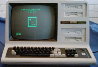
Here is a model 4 with four 3-1/2" drives installed.